
Boat Propeller 1/5: Writing the Design Brief
Once thrust and speed are settled, the pitch follows, with the slip and the matching B-series propeller: propeller pitch calculator
Part 1 · Part 2 · Part 3 · Part 4 · Part 5
To design a boat propeller, we start by writing a design brief: the cruising speed, the thrust required, the power available at the shaft and the maximum diameter. In this series of five tutorials, we build step by step, with Heliciel, the propeller of an electric pleasure boat. This first part sets the four input data, and shows how to obtain them when they appear in no datasheet.
On this page:
- Our project: the propeller of an electric boat
- The data to collect before modelling
- Finding the resistance to motion, hence the thrust
- Available power and cruising speed
- The design brief we keep
1: Our project, the propeller of an electric boat
At the end of these five tutorials, you will have the basic knowledge needed to design a marine propeller. You will also have learned to use the software, so you will be able to create aircraft propellers, ventilation fans, wind turbines or tidal turbines.
Heliciel lets us build a made-to-measure propeller from our design brief, by defining the geometry and evaluating the performance. A blade drawing, made of its profiles with their pitch angles, can be edited. A 3D model can also be produced for prototyping.
Designing a propeller calls on many skills and years of theoretical and practical experience. Yet we can carry out a project on our own, whatever our level in theory and mathematics. We take our first steps, or deepen our skills, with a propeller of respectable efficiency.
Our project is the propulsion propeller of an electric boat. Our example is a 5 metre pleasure boat driven by a motor fed from a 300 W source. This low power demands quality and efficiency from the propeller!
2: The data to collect before modelling the propeller
Before we start, we collect four data:
- the thrust we need;
- the cruising speed we hope for;
- the available power;
- the maximum diameter of the propeller.
The thrust of the propeller must match the resistance to motion of the boat at the expected cruising speed. Speed and thrust are therefore linked: we cannot choose one without the other.
3: How to find the resistance to motion and the thrust we need
Several methods exist to estimate the resistance to motion (hence the thrust we need) of a boat at cruising speed:
- The ideal is a full-size test: we tow the hull and measure the towing force over a series of speeds, up to the expected cruising speed.
- We can collect resistance data for similar boats on the internet or in the naval literature.
- We can measure the resistance of a scale model in a towing tank, then use Froude similarity to extrapolate to full scale.
- The part of the resistance due to form drag can be partly extrapolated with software such as Mecaflux. This is the dual-model method: we take an ellipsoid with the length and width of the hull, and we assume that the form drag of the hull is half that of a fully submerged ellipsoid.
- Finally, we can model the hull with Heliciel.
At this pre-project stage, we choose Mecaflux, software available on the mecaflux.com website. It is an estimate, not a measurement: it does not replace a towing test of the hull.

Mecaflux "drag and lift of profiles" screen: a 5 m by 1.5 m ellipsoid in water at 1 knot, with the drag force (23.38 N) and the power consumed (12.03 W).
4: Available power, efficiency and maximum cruising speed
Mecaflux also gives the power consumed by this drag. We have 300 W at the source. A motor has an efficiency of about 0.8, our transmission is estimated at 0.8, and we hope for 0.8 from the propeller. The overall efficiency is therefore 0.8 × 0.8 × 0.8, about 0.5. We can thus apply to the fluid a useful power of about 0.5 × 300 = 150 W.
We enter cruising speeds from 1 to 4 knots for a 5 m by 1.5 m ellipsoid. Mecaflux returns a series of form drags, which we divide by two according to the dual-model method:
- 1 knot: 23 N / 2 = 11.5 N (drag power 12 W / 2 = 6 W);
- 2 knots: 93 N / 2 = 46.5 N (drag power 96 W / 2 = 48 W);
- 3 knots: 210 N / 2 = 105 N (drag power 324 W / 2 = 162 W);
- 4 knots: 374 N / 2 = 187 N (drag power 769 W / 2 = 384 W).
With a 300 W source and an overall efficiency of 0.5, the maximum cruising speed will hardly exceed 3 knots, since the drag power already reaches 162 W at that speed. We can put the water skis away: not for today.
The 300 W is the power of the energy source. With 0.8 for the motor and 0.8 for the transmission, the efficiency between the source and the propeller shaft is 0.8 × 0.8 = 0.64. We can therefore hope for a shaft power of 300 W × 0.64 = 192 W at most. At 3 knots, the propeller will have to turn these 192 W into 162 W of useful power (105 N at 1.54 m/s), which requires a propeller efficiency of about 0.84: the target is tight, and the next parts show how close we get.
5: The design brief we keep for the boat propeller
We keep these data as our basic design brief:
- cruising speed: 3 knots, or 1.54 m/s;
- thrust required: 105 newtons;
- power available at the propeller shaft: 192 watts.
One data remains, the maximum diameter, which we set in part 2 with the constraints of the hull. We now open a water propulsion propeller model (boat) in Heliciel, from the Files menu, then New project (from a model).
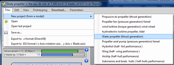
The Files > New project menu lists the models: air propeller, ventilation fan, wind and tidal turbines, axial pump, hydrofoil, wing, airship and hulls. We take "Water propeller (thrust generation)".
To go further, we can move on to part 2 of the tutorial, on the operating parameters and the geometry of the boat propeller, or review the basics on the boat propeller page.
 Global site map
 Mecaflux
 Tutorials Mecaflux Pro3D
 Tutorials Heliciel
 Tutorials Heliciel PRO CFD
 Mecaflux Store
 Compare software functions
 Quotes, Orders, Payment Methods
 project technical studies